Pipeline Design
Thrust Restraint
Pipe joints do not provide enough restraint against longitudinal separation caused by unbalanced hydrostatic and hydrodynamic forces; these forces can cause joint separation unless restraint is provided to withhold thrust forces. Thrust blocks and/or restrained joints shall be used as specified to provide restraint where pipefittings such as tees and valves are present, and where the pipe experiences considerable horizontal and/or vertical changes in direction.
Thrust Block
Thrust forces experienced with horizontal changes in direction were calculated using an internal pressure of 170 psi and were design for existing commercial bend angles (90°, 45°, 22.5°, 11.25°).
Restrained Joints
Whenever space is insufficient to fit a trust block as per on site spacing or proximity to existing utilities, restrained joints shall be used to account for trust forces when necessary.
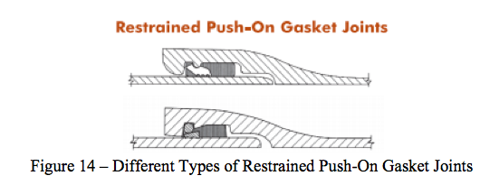
The type of restrained joint considered for the design was Restrained Push-On Gasket Joint. This joint consists of a single rubber gasket placed in a groove inside the socket at the bell end of the pipe; the other end of the pipe is pushed past the gasket, compressing it and forming a pressure-tight and dependable seal with the help of the gasket preventing leaking out of the pipe. Cross section of this type of joint is shown in Figure 14.
The type of restrained joint considered for the design was Restrained Push-On Gasket Joint. This joint consists of a single rubber gasket placed in a groove inside the socket at the bell end of the pipe; the other end of the pipe is pushed past the gasket, compressing it and forming a pressure-tight and dependable seal with the help of the gasket preventing leaking out of the pipe. Cross section of this type of joint is shown in Figure 14.